
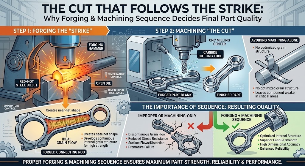
A forged blank fresh off the trimming press is not a finished part. It is a structural argument — one the hammer already won — waiting for geometry to be added. The forging machining stage is where that argument gets resolved into tolerances, surface finishes, and bore dimensions that OEM drawings actually specify. Get the sequence wrong, machine on the wrong substrate condition, or skip the traceability link between forge and machine, and the mechanical advantage that forging built into the grain structure gets wasted on a part that still fails dimensional acceptance.
The Substrate Condition Problem Nobody Talks About Enough
Every forging machining operation begins with a substrate whose properties were set hours or days earlier — during heat treatment. The order matters enormously. Machining before heat treatment means the part you dimensionally qualified will distort during quenching, because residual stresses from forging and rough machining release unevenly in the quench tank. Machining after heat treatment on a quench-and-tempered AISI 4140 shaft at 30–35 HRC requires sharper tooling, slower feeds, and tighter coolant management than the same operation on a normalized blank at 180–220 HB — but the dimensional result is stable, because the material has nowhere left to move.
For case-hardened components — helical gears, speed gears, ring gear carriers — the sequence runs deeper still. Rough machining and hobbing happen on the soft blank before carburizing, because trying to hob a 58–62 HRC case-hardened surface destroys tooling and produces no usable output. After carburizing and quenching, finish grinding restores the tooth profile to final specification, typically within 5–8 microns of the target involute geometry. That final grinding pass is not cosmetic — it is correcting the 0.05–0.15 mm distortion that carburizing and quenching introduce even on well-fixtured loads.
Tolerances That Actually Mean Something in Service
Forging machining for automotive and agricultural OEM applications does not operate on vague “tight tolerance” language. The numbers are explicit on the drawing, and the process capability has to demonstrate it can hold them across a production run, not just in a first-off sample.
Bore tolerances for transmission shafts and hubs routinely sit at IT6 grade — roughly ±0.010 to ±0.016 mm depending on the nominal diameter. At a 50 mm bore diameter, that is a total tolerance band of 0.016 mm, achieved on a CNC turning or boring operation on a forged blank that started life as a billet cut to ±2% weight tolerance. The chain from raw billet to finished bore spans a dimensional range of roughly 50,000:1, and every step in that chain either preserves or erodes the dimensional budget. Surface finish on bearing journals and gear fitting surfaces typically runs Ra 1.6 to Ra 0.8 µm, demanding consistent tool nose radius, controlled cutting speed, and stable workholding — none of which survive loose process documentation.
For flatness on flanges and coupling faces, tolerances in the 0.02–0.05 mm range across a 150 mm face diameter are standard. Achieving that on a forged blank with ±1.0 mm as-forged flash variation requires sufficient machining stock allowance on the forging drawing — typically 2.5–4.0 mm per face — to guarantee that the machined surface clears the decarburized skin layer and reaches base metal with consistent hardness. Decarburized surface layers on forged steel can run 0.3–0.7 mm deep depending on heating time and scale formation — machining through that layer is not optional if hardness uniformity on the finished surface matters.
CNC Turning, VMC, and the Tools That Connect Them to Accuracy
Modern forging machining shops do not run conventional lathes on OEM-grade work. Vertical Machining Centers (VMCs) and CNC turning centers with live tooling handle the compound geometry — cross-drilled oil passages, off-center bores, angled faces — that transmission and driveline components require. The advantage is not just repeatability; it is the ability to complete multiple operations in a single clamping, which eliminates the cumulative error that builds when a part is re-fixtured four times across four separate machines.
Tool selection for forging machining is driven by the workpiece material’s machinability rating and the heat treatment condition at the time of cut. AISI 4140 in the normalized condition (approximately 200 HB) cuts cleanly with CNMG-profile carbide inserts at cutting speeds of 200–280 m/min and feeds of 0.25–0.35 mm/rev on roughing passes. The same material after Q&T at 280–320 HB demands a reduction to 120–180 m/min and tighter chip control geometry to prevent notching at the depth-of-cut line — a failure mode that destroys insert edges and leaves surface finish outside Ra specification within 15–20 parts if not caught.
Boring operations on through-bores in gear blanks and hubs require anti-vibration boring bars at L/D ratios above 4:1, because chatter in a long boring operation leaves a characteristic helical surface waviness that shows up immediately on a profilometer trace and fails the Ra callout on the drawing. These are not edge cases — they are predictable failure modes in forging machining that disciplined process engineering anticipates and controls before the first part runs.
Traceability: The Link Between Forge and Machine That Protects Everyone
When a field failure traces back to a machined forging, the investigation moves in two directions simultaneously — toward the machining process and toward the original forged blank. Without documented traceability connecting the finished machined part to its forging lot number, heat treatment batch, and raw material heat number, that investigation hits a wall within 48 hours. With it, the failure analysis team can correlate the failed part’s spectrometer chemistry, hardness test records, and dimensional inspection data against the production run it came from, identify whether the failure is systemic or isolated, and contain the risk accordingly.
Sendura Forge Pvt. Ltd., operating under IATF 16949:2016 and ISO 9001:2015 certification from Rajkot, Gujarat, manages this traceability chain from optical emission spectrometer analysis at billet intake through forging lot documentation, heat treatment batch records, and finished goods certificates of conformance — serving OEMs including DANA, Mahindra, Eaton, New Holland, and TAFE across automotive, agricultural, and power transmission applications with a product range exceeding 700 active part numbers.
Why One-Facility Integration Changes the Quality Equation
Forging machining done under a separate roof from forging introduces a structural quality risk that no inspection protocol fully eliminates. Dimensional drawing interpretation gaps between the forge supplier and the machine shop produce forged blanks with insufficient stock on one feature and excess on another. Inter-facility handling damages critical reference surfaces — datum faces, bore entries — that the machining operation depends on for accurate fixturing. And when a machined part fails dimensional acceptance, the question of whether the root cause lives in the forging geometry or the machining process takes weeks to resolve across two separate quality systems.
Single-facility integration — forge, heat treat tie-ups, and machining capability under one quality management umbrella — keeps the dimensional chain short and the accountability clear. The forging drawing and the machining drawing are authored with knowledge of each other, stock allowances are calibrated to the actual as-forged variation the hammer produces, and a non-conformance at any stage triggers a single corrective action record, not an inter-supplier dispute. For OEMs managing supplier risk across 50- or 100-part numbers, that structural clarity in the supply chain is not a soft benefit. It is an audit finding waiting to happen if it is absent.
The Measurement Infrastructure That Closes the Loop
No forging machining process controls what it does not measure. Brinell hardness testing on forged blanks before machining confirms the heat treatment cycle achieved the specified hardness band — at 280–320 HB for Q&T 4140, or 160–200 HB for normalized 1045 — before cutting tools engage a substrate that might be either too hard for the programmed parameters or too soft to hold the specified surface finish. Magnetic particle testing on finished machined shafts and cross shafts detects surface and near-surface cracks that originated in the forging process but become critical only after machining exposes them at a stress-concentration feature like a keyway root or an undercut bearing journal. Universal testing machine data on tensile specimens from forging lots validates that yield strength and elongation meet drawing requirements before those lots enter the machining queue, not after.
The measurement loop in precision forging machining runs from incoming billet chemistry through process-stage hardness checks, to final dimensional and surface inspection on the finished component. Closing every link in that loop is not overhead — it is the only mechanism that makes delivery of consistent, traceable, OEM-grade parts repeatable at production volume rather than sample scale.


